
UV curing of conformal coatings can appear to be a complicated topic, however, a few simple steps will help to correctly set up your production process. The main difference between UV curable coatings the traditional cure mechanisms is the utilization of UV energy to effect the change from a liquid to a solid. After this rapid UV curing step the coating is tack-free and the PCB can continue its production journey negating any requirement for long curing, post-bakes etc.
Getting Started with UV curing
The three most important variables to be concerned with during UV curing are the correct wavelength, the intensity of light, and the total time spent under the UV light.
To achieve the correct wavelength, there are two options for oven lamps: arc or microwave. Each has its own unique advantages and disadvantages. An arc lamp requires high voltage and high current to energize a mercury lamp to produce UV light, while a microwave lamp uses an electrodeless design. When choosing a curing lamp, engineers should consider bulb longevity, start-up time, dimensions, and initial costs (Figure 1). The choice of UV lamp type is secondary to curing, as long as the three above-mentioned variables are achieved (wavelength, intensity, time).
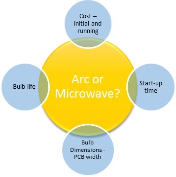
Figure 1. Arc or Microwave lamp technologies
HumiSeal UV curable coatings can be cured correctly with either lamp technology as long as the minimum irradiance (intensity) and total UV dose (time) are met (Table 1). To ensure this, the correct UV bulb must be used inside the lamp to deliver the desired wavelengths to initiate the curing reaction. The correct bulb choice is mercury (Hg) which delivers the dose and intensity in the correct wavelengths to ensure complete curing.
Setting up your UV Oven
The main factors to consider when setting up your UV oven are the conveyor speed and the height of the bulb from the conveyor. The conveyor speed influences the total energy delivered and also your coating line throughput. The conveyor speed must be balanced to ensure the right amount of energy is delivered and good throughput is achieved. Typical conveyor speeds are in the 1.0 – 1.5 m/min range.
The height of the UV lamp from the PCB surface governs the intensity of UV light. Intensity is inversely proportional to the distance squared from the lamp and the focal length. Like focusing the sun with a magnifying glass, the further from the subject matter, the less focused the energy. However, due to the constraints of standard PCB component heights, the typical distance above the lamp should be 70-110 mm. Lower height may increase heat transferred to the PCB, potentially damaging components. Too high above the PCB surface and the UV intensity will be dispersed, making it ineffective to cure the coating. If this situation occurs, the coating will often come out tacky immediately after UV curing.

Figure 2. PCB Component Height Affects Lamp Height Set Up
UV Dose and Irradiance Measurement
A key part of the initial setup of a UV curing oven is the measurement of the Dose and Irradiance using a radiometer.
- Dose measured in J/cm2, is the total energy received as the radiometer passes through the UV oven
- Irradiance measured in W/cm2, is the peak energy (intensity) received as the radiometer passes through the UV oven
Like any controlled process, this measurement should be done at setting up and then at regular intervals as part of SPC. This measurement is the baseline for any UV curing process. The radiometer is placed on the conveyor in the same position, height, and orientation as a PCB and passes through the UV oven to simulate the dose and intensity that the coating is receiving. If the dose and irradiance figures are outside of the given specification (Table 1), then the coating will not be cured completely. Lower than the recommended specification and the coating will remain tacky after UV curing. Higher than the specification and there is a risk of damaging the coating and the PCB itself (excessive heat).
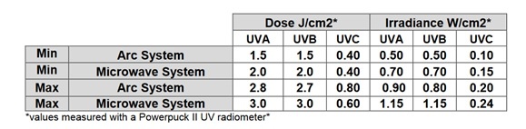
Table 1. Minimum and Maximum Dose and Irradiance
The radiometer readout is split into four wavelength ranges: UVA, UVB, UVC, and UVV. The most important are UVA, UVB, and UVC.
- UVA and UVB are longer wavelengths and can pass through the coating and cause polymerization
- UVC is a shorter wavelength and reaches the surface of the coating to provide the tack-free coating surface

Figure 3. Radiometer Measurement Readout
In summary, it is important to ensure that your UV cure system delivers the required level of irradiance and total energy to the coating at the right wavelengths. The correct curing setup will ensure the coating will be tack-free and the PCB undamaged to allow for mass production to begin.


